Design for Manufacturing Series: Subtractive Machining
In an article published a few weeks ago (1), I gave a brief overview of a variety of manufacturing processes. The sheer number and depth of manufacturing processes deserve so much more than I was able to write in that article. So now, I will further discuss the first set of processes – subtractive machining.
Interested in reading the overview? Find it here.
Introduction
Subtractive machining is one of the most basic manufacturing processes, involving only the removal of material from blank stock. Because it’s so basic, it has existed since ancient times, the first machine invented for this process was the lathe. The first recorded instance of the lathe was in ancient Egypt in 1300 BCE, used to cut shapes into pillars of wood. As the Middle Ages and the Industrial Revolution passed, the lathe went through phase after phase of development, as seen in the images below (2).
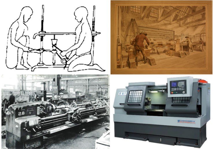
Image 1: Progression of the lathe through history. Top left: Egyptian Lathe, Top Right: Middle Ages Lathe, Bottom Left: Industrial Revolution Lathe, Bottom Right: Modern CNC Lathe
Besides the lathe, subtractive machining can be done with all sorts of tools that generally fall into two categories. First, manual subtractive machining, or machining done without pre-programmed tool paths, is accomplished through hand tools, drill presses, and cutting implements. The design, tolerances, and processes of manual machining are only limited by the operator’s skill. The other is Computer Numeric Controlled (CNC) machining which is accomplished by using software to preprogram all of the tool paths needed to manufacture a part and implementing those tool paths in a computer-controlled machine. The design, tolerances, and processes of CNC machining are limited by the machines you have access to and your skill with the necessary software. In this article, due to the advanced nature of CNC machining, I will focus on that category of subtractive machining. Designing and producing parts for manual machining varies from project to project, but there are a few general guidelines that can be applied to every CNC project.
Design and Process
When designing for CNC Machining, the most important thing to remember is that the tool is coming down perpendicular to the face of the stock to be machined. Because of this, there are a few limitations that must be considered when designing your CNC part. First, a good design should eliminate as many undercuts as possible. An undercut is a recessed or sunken feature in a part, as in the picture below.

Figure 2: (left) Graphic showing undercuts in a milled part, (right) lollipop mill capable of producing undercut features
Because the tool comes down to the face of the stock perpendicularly, the tool is unable to cut outside of its profile, i.e. the overhangs created by the angled wall and the two key slots on the right side of the part (above). It should be noted that there are a few types of tools that can manufacture a slight undercut, such as the lollipop-shaped tool on the right of the above picture. However, this is only recommended if the undercut is critical to the function of your part.
CNC machines are also built with speed and precision in mind. Consequently, operations and features should be optimized to enable as much of those two as possible. Features – such as corners, fillets, and edges – should be designed with the largest radii possible. “This helps avoid the need for specialist tools and ensures faster processing,” (3) because a larger tool can remove more material at a time. Cavities in your part should also be no more than four times deeper than their width. The longer a tool is, the more chatter or vibration will occur at the end of the tool, causing more variation and interference and can cause your part to fail.
Another design consideration is the thickness of the walls of your part. Decreasing the thickness of walls also decreases their stiffness as well. “[D]ecreasing the wall thickness reduces the stiffness of the material, thus increasing vibrations during machining and [lowering] the achievable accuracy” (3). While metal is a strong and generally stiff material, at the high speeds at which most CNC machines run, vibrations can occur through the slightest imperfection in movement or material. As you are designing, a good guideline for minimum wall thickness is .8 mm (.031”) for metals and 1.5 mm (.059”) for plastics; as these thicknesses will provide enough rigidity in your parts to prevent bowing, unwanted subtraction, and failed parts.
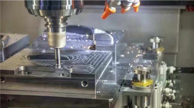
Image 3: Aluminum stock undergoing CNC milling
A final design consideration that you should take when designing a part to be CNC machined is that the smaller a feature is, the harder it is to manufacture. Similar to the reasons behind wall thickness design, chatter and vibrations can cause serious issues to miniature features. If you can make your features larger than 2.5 mm (0.1”), you will be able to use standard tools and simplify your manufacturing process. If you absolutely must include small features in your product, there is still a good chance you can produce a successful product, you will just have to use specialized tools and have a high level of CNC machining experience (3).
Machines and their applications
Now that we know the parameters for subtractive manufacturing, let's learn about some of the machines used in this manufacturing process. Most commonly, subtractive machining is performed with CNC mills. These machines utilize various types of tool bits to subtract material on the horizontal plane (called 3-axis mills). There are also 5-axis mills that enable you to machine a part on five sides (i.e. every face but the bottom face).

Image 4: Depiction of a Haas CNC Mill (3-axis)
Some common applications of 3- and 5-axis mills are plastic injection molds, airplane parts, and consumer electronics components. After CNC mills, the next most common machine is a CNC lathe. The bottom right section of the first image is an example of one of these lathes, which can produce automotive parts, ball joints, and nuts and bolts. Another form of CNC machining is Electrical Discharge Machining (EDM), which as we discussed in the last manufacturing article, can be ram or wire EDM (1). This process is excellent for producing sharp inside corners, parts made out of plate metal, and extremely fine details. All of the parameters we discussed above, aside from undercut features, can be successfully produced through the EDM process. CNC machines also include routers (for milling materials other than metal), laser cutters (to quickly cut through sheet material), and grinders (for fine machining of hardened metal parts).
Conclusion
When you are designing a part and you want to manufacture it through subtractive machining, remember these things: eliminate undercuts, optimize your parts for speed and precision, and reduce reliance on miniature features. If you do this, you will end up with a successfully manufactured part.
References:
1 A Brief Overview of Manufacturing Processes
2 https://blog.mmi-direct.com/machining-history-lathe-the-mother-of-all-tools
3 Design for CNC Machining: Restrictions & Considerations
To cite this article:
Cousins, Andrew. “Design for Manufacturing Series: Subtractive Machining.” The BYU Design Review, 9 Feb. 2024, https://www.designreview.byu.edu/collections/designing-for-subtractive-machining.